For a number of years I have been actively involved in the building of the 1990s based layout called Farkham. The layout has been to a significant number of exhibitions around the UK and Europe but has now reached the end of its lifespan as an exhibition layout. As a result my attention (and those of my fellow Farkhamites, Alex and Dave) has drifted to new ideas to keep our creative modelling juices flowing. We have now embarked on individual projects of differing (and in some cases dubious) subjects, this blog recording my ramblings on the attempts, errors and successes that I have had during the construction of my own project.
I hope that the forthcoming entries are of interest to readers, I will try and keep the entries as up to date as I can but sometimes the modelling just gets in the way.
Thanks for reading
Paul.
Background & Philosophy
My interest in model railways goes back to being a kid at school and my specific interest in the period of 1988-1991 really centres around the time when my interest in the real railway peaked. This also coincided with a time when there was a culmination of loco liveries ranging from rail blue, Railfreight, large logo, NESE, Intercity, Scotrail and Sectorisation. The end of the period of interest also coincided with the end of the Speedlink era and the loss of the mixed Speedlink workings between freight yards.
My interest in this period has meant that I currently have a significant amount of stock from that period and therefore (with some reworking) this will be useable for SPLOTT.
In writing this blog, admittedly the majority of it being retrospective, I was trying to think about how the layout actually developed into the form that it is now. Long have I been interested in freight stock, I developed an interest in scratchbuilding wagons for Farkham and several of these were related to steel traffic. I guess that this leaning towards the ferrous coupled with an interest in ‘shunting the yard’ at exhibitions lead me to design and construct a small steel yard.
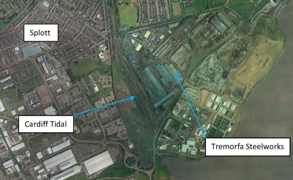
Why the region? – South Wales. This was not somewhere that I had originally envisaged modelling and it was only by chance that my satnav took me on a diversion (avoiding some traffic jam or other) whilst trying to get to a meeting in the centre of Cardiff. The route took me around the outskirts of the city, on a road called Rover Way which runs parallel to the Tremorfa Steelworks and passes over the south end of Cardiff Tidal yard. Further investigations of the site (partially whilst sat in the meeting (someone was talking about pipes and wires no doubt!)) enabled me to have a look on Google Earth at the facility I had just driven past. This showed a whole host of tracks going into and out of buildings and also the adjacent yard. Now as much as I would have liked to undertake a model of Cardiff Tidal and the adjacent works, sadly space at home does not permit such an enterprise, however the seeds of the idea were planted and quickly took root. Further views on Google Earth also highlighted the nearby housing estate and its interesting name, Splott. This, I decided was to be the name for this venture as it’s a bit quirky, it implies the location (to those who know where Splott is) but does not suggest that this is a model of Cardiff Tidal or Tremorfa Steelworks.
Trackplan
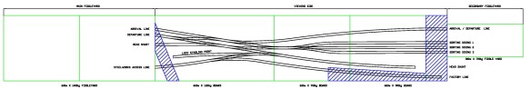
The trackplan is a relatively simple and comprises of In and Out lines emanating from the fiddle yard at the right hand side of the layout (when viewed from the front!)
The nearest line to the viewer is the reception and departure road, whilst the upper three lines are the sorting sidings. the remaining lines comprise of headshunts, a loco stabiling siding and a departure road at the top right which is destined to serve the ‘wider works’ (not modelled) with trip working services as a way to justify additional freight wagon modelling interest.
Baseboards
Having been used to lugging about a 28’ lump of a layout to more than 50 shows for the last 10 years, I had decided from the outset that the layout would need to be relatively simple to erect, dismantle and transport. To this end, I decided to construct the layout baseboards, supports, backscenes and lighting frames all at the same time. Previous layout baseboards I have built have utilised common 2×1 frames with chipboard tops or more recently plywood sides and bracings with an MDF lid. For this project, I chose to have a crack at using the baseboard construction methods described in the Wild Swan publications by Iain Rice and Barry Norman which consists of essentially creating ply and softwood boxes for the frame with a ply top. Whilst my woodworking skills are no better than average at best, the boards certainly seem to be a lot stiffer than previous methods and whilst it may have taken longer to construct and used slightly more material, it is certainly a method that I would definitely use again, that’s not to say of course, that there isn’t another alternative to try out. Maybe the insulation sheet and ply frame next time!
Within the frames of the boards, I designed the ends of the scenic sections to protrude above baseboard tops so that this would form both the scenic end protection board and also the support for the backscene. Similar vertical (2×1 softwood) supports also protrude out along the back of the layout to support the backscene along the length of the layout.


All of these protrusions also provide support to the lighting framework which is constructed using 4mm ply built into a lattice shape with a hardboard sheet to the underside. Small holes were drilled through the cross members to enable wiring to pass through and reduce weight in the frame so that the minimum amount of deflection would occur in the lighting unit once erected.
The supports for the layout were the next item to be constructed. On the previous layout, integral fold up legs were installed. These worked fine but proved to be awkward to erect and dismantle when limited assistance was available. I therefore decided to opt for a simpler separate typo of support arrangement. This comprises of a pair of legs constructed in 2×2 softwood with a spacer plate of 9mm ply. There are 5 pairs of these elements to support the layout. When the layout is to be erected, the first two pairs of legs are bolted together using horizontal and diagonal bracings of 2×1 softwood. Once bolted tight, this provides a stable frame with ‘sway resistance’ in the long direction of the layout, the ‘sway’ on the other direction is resisted by the ‘stiffness’ or ‘diaphragm action’ of the 9mm ply sheet fixed to the legs.
At the top of each leg is a vertical slot which is cut just slightly wider than the thickness of the plywood used in the baseboard frame. The inserted leg is then held vertically by softwood blocks fixed within the baseboard frame. This also takes up slop in the frames and therefore helps to prevent the layout from wobbling.
Baseboard connections utilise the common pattern makers dowel connection, something that I would always choose to utilise on every layout that I build. With a relatively thick framework under the layout, I went to B&Q looking for bolts to lock the boards together. For some reason I ended up buying and using some 10mm bolts, washers and wingnuts. I cannot remember what the driver for this choice was but every time I connect these bolts up, I wonder why I picked such a large diameter bolt – ‘they would not look out of place holding up a warehouse frame’. I guess it must have been the length of the shank that mattered. Food for thought for future projects!.
In hindsight, I think that it would have been better to make the baseboards another 20mm deeper so that there is more protection to the point motor connections as they are vey close to the bottom of the baseboard line.
Trackwork
Before I begin to describe the trackwork, I thought I would mention the sub-base to the track. Long have I used cork sheet or cork tiles as the base for the track (although in the earliest Spencer layouts, Hornby underlay has made an appearance, some may say that this looked better than my earliest (and indeed more recent) attempts at ballasting), I am not sure why, I just have!. I guess that using a layer between the baseboard top and the underside of the track gives me a bit of vertical breathing space in the levels between the track and the baseboard surface (albeit only a few millimetres) but it allows for a ballast shoulder if its needed or a few divots and puddles within the scenic to create a bit of interest. Instead of cork for the sub-base, I decided to use some medium density styrene sheet. Its real purpose is as underlay for laminate flooring and it comes in 5mm thick sheets. It is relatively dense and therefore is resistant to a reasonable amount of pressure being applied to the surface. It is not however resistant to Butanone, Plastic Weld or Evo-stick!! I was hoping that this material might also help to reduce track noise on the layout. Whether it works or not remains to be seen. Another advantage of a sub-base is that wires and droppers can also be recessed into this material if necessary, where say a proposed dropper hole coincides with a below board bracing member or a point motor etc.


On to the track. For this project, which is not a massive ensemble, I decided to venture into the dark arts of P4 modelling. This step was not taken lightly. I saw this as a challenge to my modelling skills and have relished to opportunity to have a go at building my own track and points. Here I must admit that I have cheated somewhat in that whilst I have built the trackwork myself, I did purchase the points as (unbuilt) kits from Exactoscale and similarly with the trackbases, I used the plastic sleeper types rather than copperclad or real timber sleepers. The threading of the chairs in the correct orientation onto the rail being a mind numbing job.
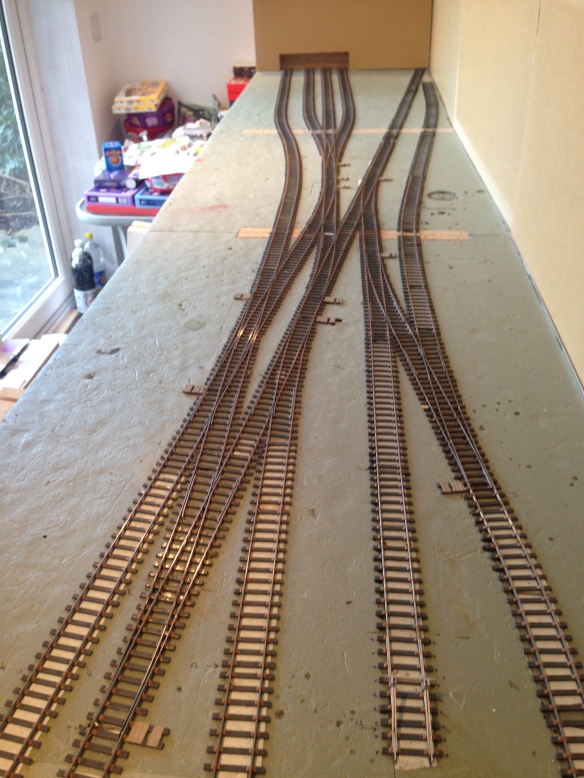
Building the point kits was easier than I expected it to be and I would not let this put you off building a P4 layout if you so wished. The biggest eye-opener for me with this trackwork construction was the number of droppers required to actually get power to each element of the track. There are loads of them. I used a steel sewing pin with the head filed flat and then soldered to the underside of the rail.
Of the points on the layout the majority of them are B6 or B7 points but there is also a single slip and a 3 way point. The latter being constructed using 2 B6 point kits and an A5 crossing. Expert advise at the time of purchase was provided by Len Newman (Mr Exactoscale) who was most helpful.
For the tie-bars on the points I utilised the etched tie bar connectors developed by Ambis. They were rather tricky to construct and a number of attempts were made before finally getting the bend and folds correct. The two etches were soldered to the point blades and a thin piece of paxolin strip was inserted between the blades to complete the assembly, hopefully without generating electrical contact.
Wiring and Control
As I eluded to earlier, there were masses and masses of dropper wires from each of the track sections. Each dropper, having been soldered to the underside of the rail was placed through a hole in the baseboard top. The projecting pin enabled new wires to be connected to the rest of the layout wiring system. Once connected the pin and the hole were fixed to the baseboard using hot glue from a glue gun. This would then prevent ballast and liquid running through the holes in the baseboard.
The control for the layout is intended to be DCC, utilising the NCE powercab system. Who said that a DCC layout only needs two wires??. The reality seems to be somewhat different.
In respect of point control, I have utilised the Cobalt point motors. These are stall motors and I decided that these would NOT be controlled using DCC, rather using a simple ON-ON toggle switch on the control panel. The motors have two auxiliary switches within their design and these are used for controlling the polarity of the crossing vee. The ON-ON toggle switches were double pole switches and therefore one side of the switch controlled the firing of the point and the other side controlled the colour of the LEDs on the panel (red or green). This effectively gives a route setting diagram on the panel. Whilst there are eleven point motors controlling the various points, these have been interlocked such that multiple points are controlled through single switches ensuring that one point is not set against another and that polarities of adjoining tracks are therefore always the same.
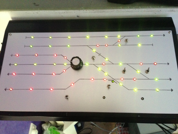 On the 3-way point, I have used a rotary switch set for the 3 roads rather than using two toggle switches. This works well for the point control but in terms of controlling the LED colours this has exceeded my limited electronics knowledge. I am sure that there is some simple gizmo out there that would easily solve the puzzle – I just don’t know what I am looking for!
The layout itself is split into two control districts using NCE circuit breaker boards. This limits the effects of short circuits on the layout (not that there will be any of course!!!).
Control of the layout is from a single control panel mounted at the front left of the layout. This controls the points on the layout. DCC controller sockets are provided adjacent to the panel on the front left but also at the front right and again in the fiddle yard where here is also a programming track.
Buildings and Scenics
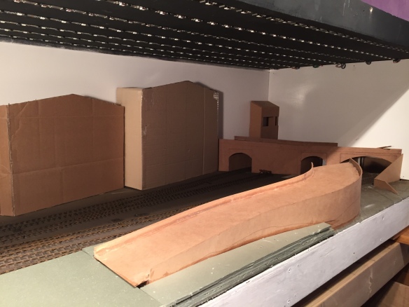
One of the things I enjoy about model railways is being creative and building the scenery, structures and little cameos is my favourite part of the process. Having an idea about the scenics before I start is vitally important, thinking about how I am going to cover the access from the fiddle yards effectively and also disguising / masking / deflecting views away from the inevitable (unless I built a 10ft board) board joins are key to the process. Sketching out some ideas before I started, then converting this into a 3D mock up using all sorts of implements gave me a good fee for what is working and what wasn’t without having wasted time building something that I wouldn’t use. Its easy to move the breadsticks and pickle jars about as much as you like!!!


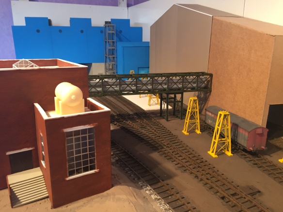
Once I had the basic idea in mind, I set about constructing the principal buildings. I decided to work from the left as this is the end that I was most certain about. So I started to construct the main blue factory which runs across the end of the layout. This was inspired by photos of Velindre steelworks, Ebbw Steelworks and the roof profile of the steelworks at Tinsley that runs parallel to the M1 at meadowhall. I formed the carcass of the building using thin MDF and then clad the outside with profiled evergreen cladding to the upper levels and plain sheet to the lower levels which would become concrete. The completion of this initial work coincided with a visit from my nephews who always like to know how things are progressing with the layout. I proudly showed them my latest endeavour, “Is it a castle” Tom asked, “No” I replied, deflated. “Well shouldn’t it have something inside it then?” came the response from James. The random statement sent my mind into overdrive (not a regular occurrence) and so I decided that where possible I would detail the internals of the buildings on the layout too – not something that I had done before. So I set about constructing the inside of the factory using Plastruct, Evergreen and elements of a Cornerstone rolling mill set.


With the interior substantially complete, I fitted this within the shell of the building and put the roof on. Great – the only issue was – it was too dark to see the interior. This led me to my next task of trying to put lights in the buildings. Talk about making a rod for your own back, now I needed to build the buildings, detail them, paint and weather them, add interiors and now add lights to them. “Its all part of the fun” – keep telling yourself that!.


With this first building completed, I progressed onto the other structures on the layout, the majority of them being constructed using similar methods all being scratchbuilt, with the exception of the single storey office block (which I started to build only to find that Bachmann had produced one exactly the same – so I bought that and tarted it up). The other purchased items were the brick chimney (lifes too short to try and scratch build one of these) the security hut on the road and finally the 3 sections of white tank at the rear centre of the layout.
The road bridge over the main tracks depicts a steel girder bridge within infill vaulted brick arches beneath. (not that they can be easily seen!). This was drawn in 3D CAD and then printed in one piece using ‘strong flexible plastic’ printed by Shapeways.
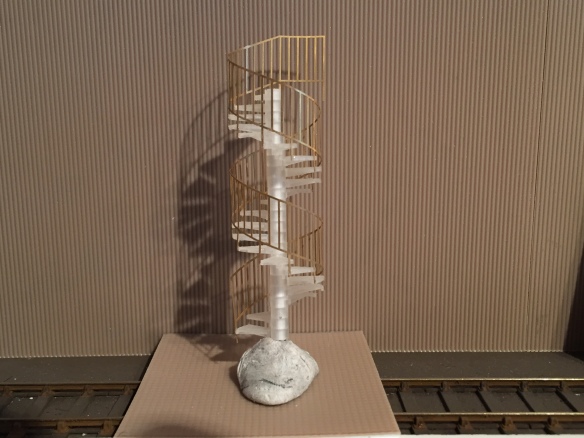
Similar drawing work was undertaken for the spiral staircase and this was again printed by Shapeways, this time using FUD. Originally, this staircase was going to sit inside the boiler house at the front of the layout, but it was pointed out by a friend that no one would see it, so its location was changed (for the better – but don’t tell him!).
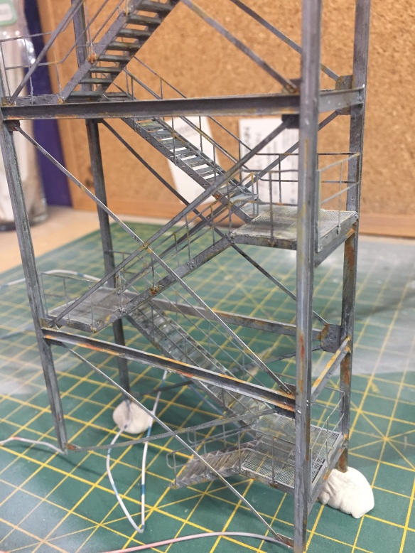
The other staircase is a multi-level external staircase based upon a real structure. Made from etched brass and stainless steel, the structure comprises of around 300 individual components which have been soldered (in the case of the brass) and glued in the case of the stainless steel (what a wimp I hear you shout) together to for the flights up to the roof. The stair is sprayed with a dull silver to reflect galvanised paintwork and then weathered with rust colours at the locations which are most exposed or where water collects. This was one of my favourite elements to build on the layout.
The pipe gantry which spans across the layout (hiding the board joint) is a Noch product which is a laser-cut card kit of a steel truss bridge with various bits lopped off. The pipework is acrylic tubes with 3D printed bends and Tees fitted to form the runs along the inside of the duct. The whole section is removable as is the section over the top of the building which is attached to the model with small magnets.
The brickwork retaining walls supporting the highway are constructed using layers of slaters plasticard with individual styrene coping stones. The pavement is constructed using 4.8mm wide strip cut into 8mm length sections to form the paviours. There are approximately 640 individual stones placed (that’s one Sunday afternoon I wont get back!). The road surface is formed using a textured paint made by AK Interactive called “Asphalt”. The road markings were then sprayed on and the whole surface weathered with weathering powders.
The street lights were purchased from ‘Layouts4U’ and were enhanced with additional base sections which were drawn in Cad and then 3D printed. These were wired up ready for use.
The vehicles on the layout are all from the Corgi collectibles range, each has been weathered and matt/satin varnished to dull them. The vehicles on the highway also have working headlight and tail lights which were 0603 and 0803 prewired LEDS fitted into the bodies of the vehicles. Whilst the supply for these was 12V, it was necessary to use a voltage regulator to reduce the supply and ‘scale down’ the lux level of the lights. All too often do you see lights on layouts that are so bright that they dominate the scenic around them.
The yard lights (of which there are three) are the N Brass Loco yard lights (quite why N Brass is called what it is – I have not idea and they must lose lots of custom from 4mm and 7mm modellers who think they only sell N gauge items). They have been adorned with the lamp fittings from more of the Layouts4U and then wired through the frame to electrical connections below the layout.
The ballast used on the layout is Woodland scenic fine cinders which has been glued in place with a couple of coats of Pledge floor polish (the modern equivalent to Johnsons Klear).
The vegetation on the layout utilises Mini-Natur 2mm, 4mm and 6.5mm long static grass fibres in a variety of colours. The Greenscene static grass applicator being an invaluable tool for this. To create patches of brambles, I utilised hanging basket filler material glued and teased out, then painted brown before being scattered with Woodland Scenic ‘weeds’ colour scatter. The other patches of weeds, Gauze, Rosebay Willow Herb, Buddleia and Nettles are all based upon the principles described in the excellent books written by Gordon Gravett. Sadly, the trees on the layout are not based upon these high standards (maybe for the next layout), rather they were purchased off the internet from a company in Poland. They do however give a good impression of trees and add some height and colour to the layout.
Here are some pictures of progress to date


Layout Lighting
The lighting on the layout is provided using LEDs. These LEDS are provided in seven strips of 83 LEDS (totalling 581 LEDS) supported from the layout lighting gantry. The LEDs are 5050s and are DMX LEDs meaning that they can be controlled individually (if so wished) using a programmer and computer software to give any arrangement of colour or movement.
The software enables a window to be placed over any picture, video or other media and this then grabs the patterns/colours and converts them into a file for the LEDs to replicate. Clearly if I had purchased and installed 1080 LEDS along the layout and 720 rows of LEDS across it, I could have created a HD TV lighting system. Whilst this sounds pretty cool to try, I am not sure about the practicalities, benefits or justification of the cost!!
